Detail Description of Guided Media
Guided Media
v The most common type of cable used in data communications is copper.
v There are different types of copper cable but they all share the feature of transmitting data as an electrical signal. This gives rise to one of the weaknesses of this type of media, which is that sending an electronic signal causes heat that is absorbed by the media as the signal travels thus causing signal loss, i.e. attenuation.
v The faster the data transfer rate over copper cable the greater the possibility of signal loss and interference.
v Guided media are manufactured so that signals will be confined to a narrow path and will behave predictably. Commonly used guided media include twisted-pair wiring, similar to common telephone wiring; coaxial cable, similar to that used for cable TV; and optical fiber cable.
v The purpose of the physical layer is to transport a raw bit stream from one machine to another.
v Various physical media can be used for the actual transmission. Each one has its own niche in terms of bandwidth, delay, cost, and ease of installation and maintenance.
v Waves are guided along a solid medium such as a transmission line.
v We will look at all of these in the following sections.
Twisted-Pair
v A plastic coating on each wire prevents the copper in one wire from touching the copper in another.
v The twist helps reduce interference by preventing electrical signals on the wire radiating energy (causing interference) and by preventing signals on other wires interfering with the pair.
v The historical foundation of the public switched telephone network (PSTN) lies in twisted-pair, and even today, most people who have access to networks access them through a local loop built on twisted-pair.
v Twisted pair cable most used in modern Ethernet networks
v Although twisted-pair has contributed a great deal to the evolution of communications, advanced applications on the horizon require larger amounts of bandwidth than twisted-pair can deliver, so the future of twisted-pair is diminishing.
Characteristics of Twisted-Pair
v The total usable frequency spectrum of telephony twisted-pair copper cable is about 1MHz (i.e., 1 million cycles per second).
v Newer standards for broadband DSL, also based on twisted-pair, use up to 2.2MHz of spectrum. Loosely translated into bits per second (bps)—a measurement of the amount of data being transported, or capacity of the channel—twisted-pair cable offers about 2Mbps to 3Mbps over 1MHz of spectrum.
v But there’s an inverse relationship between distance and the data rate that can be realized. The longer the distance, the greater the impact of errors and impairments, which diminish the data rate. In order to achieve higher data rates, two techniques are commonly used:
 The distance of the loop can be shortened, and
 Advanced modulation schemes can be applied, which means we can encode more bits per cycle.
v New developments continue to allow more efficient use of twisted-pair and enable the higher data rates that are needed for Internet access and Web surfing, but each of these new solutions specifies a shorter distance over which the twisted-pair is used, and more sophisticated modulation and error control techniques are used as well.
v Another characteristic of twisted-pair is that it requires short distances between repeaters. Again, this means that more components need to be maintained and there are more points where trouble can arise, which lead to higher costs in terms of long-term operation.
v Twisted-pair is also highly susceptible to interference and distortion, including electromagnetic interference (EMI), radio frequency interference (RFI), and the effects of moisture and corrosion. Therefore, the age and health of twisted-pair cable are important factors.
v The greatest use of twisted-pair in the future is likely to be in enterprise premises, for desktop wiring. Eventually, enterprise premises will migrate to fiber and forms of wireless, but in the near future, they will continue to use twisted-pair internally.
There are two types of twisted-pair:
v UTP (Unshielded twisted pair)
v STP (Shielded twisted pair)
1) UTP (Unshielded twisted pair)
v Unshielded twisted pair (UTP) is the most popular and is generally the best option for school networks.
v The quality of UTP may vary from telephone-grade wire to extremely high-speed cable
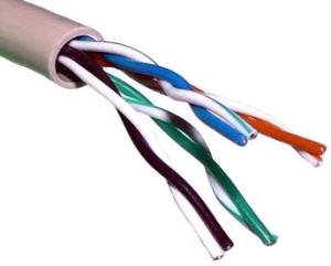
v . The cable has four pairs of wires inside the jacket. Each pair is twisted with a different number of twists per inch to help eliminate interference from adjacent pairs and other electrical devices.
v The tighter the twisting, the higher the supported transmission rate and the greater the cost per foot.
v UTP is particularly susceptible to crosstalk that means signals from one line may get mixed up with signals from another.
v Attenuation of the signal is the biggest problem.
v UTP cables are capable of supporting different bandwidths and transmission speed.
Categories of Unshielded Twisted Pair
|
Category
|
Speed
|
Use
|
|
1
|
1 Mbps
|
Voice Only (Telephone Wire)
|
|
2
|
4 Mbps
|
Local Talk & Telephone (Rarely used)
|
|
3
|
16 Mbps
|
10BaseT Ethernet
|
|
4
|
20 Mbps
|
Token Ring (Rarely used)
|
|
5
|
100 Mbps (2 pair)
|
100BaseT Ethernet
|
|
1000 Mbps (4 pair)
|
Gigabit Ethernet
|
|
|
5e
|
1,000 Mbps
|
Gigabit Ethernet
|
|
6
|
10,000 Mbps
|
Gigabit Ethernet
|
Unshielded Twisted Pair Connector
v The standard connector for unshielded twisted pair cabling is an RJ-45 connector. This is a plastic connector that looks like a large telephone-style connector (See fig. 2). A slot allows the RJ-45 to be inserted only one way. RJ stands for Registered Jack, implying that the connector follows a standard borrowed from the telephone industry. This standard designates which wire goes with each pin inside the connector.
2) Shielded Twisted (STP)
v Each pair of wires is individually shielded with foil.
v There is a foil or braid shield inside the jacket covering all wires (as a group).
v There is a shield around each individual pair, as well as around the entire group of wires (referred to as double shield twisted pair).
v STP includes shielding to reduce cross talk as well as to limit the effects of external interference.
Application of STP
v The STP cable is used in networks where cables pass closer to devices that cause high EMI.
v It covers the distance of same 100 meter as UTP
Advantage of STP
v STP is less susceptible to electrical interference and supports higher transmission rates over longer distance than UTP.
v Less susceptible to noise.
Disadvantage of STP
v Materials and manufacturing requirements make STP more expensive than UTP.
v Extra protection provided by shielding however, limits the wire’s flexibility.
v Shielding make it somewhat harder to install.
Coaxial Cable.
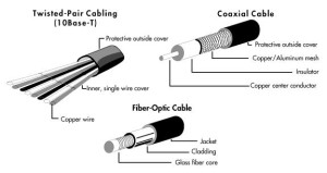
v A coaxial cable consists of four concentric cylinders: an inner conductor, surrounded by an insulating cylinder, surrounded by an outer conductor, surrounded by a final protective cover. This combination is called a coax (following figure).
v Coaxial cables are superior to twisted pairs both in terms of bandwidth and communication distance, and can provide bandwidth to distance ratios in order of 10s of MHz per kilometer. Like twisted pairs, multiple coaxes are usually housed within one cable, which may also contain twisted pairs. Coaxial cables are extensively used in LANs and long distance telephone trunk lines.
v A second type of copper wire is coaxial cable, similar to that used for TV aerials. The coaxial cable provides better protection from interference by providing a metal shield as illustrated in above figure.
v The metal shield forms a flexible cylinder around the inner wire providing a barrier to electromagnetic radiation, both incoming and outgoing. The cable can run parallel to other cables and can be bent round corners.
There are two types of coaxial cable
v Thin (Thin net):- Thin coaxial cable is also referred to as thinnet. 10Base2 refers to the specifications for thin coaxial cable carrying Ethernet signals. The 2 refers to the approximate maximum segment length being 200 meters. In actual fact the maximum segment length is 185 meters. Thin coaxial cable has been popular in school networks, especially linear bus networks.
v Thick (thick net):-Thick coaxial cable is also referred to as thicknet. 10Base5 refers to the specifications for thick coaxial cable carrying Ethernet signals. The 5 refers to the maximum segment length being 500 meters. Thick coaxial cable has an extra protective plastic cover that helps keep moisture away from the center conductor. This makes thick coaxial a great choice when running longer lengths in a linear bus network. One disadvantage of thick coaxial is that it does not bend easily and is difficult to install.
Coaxial Cable Connectors
The most common type of connector used with coaxial cables is the Bayone-Neill-Concelman (BNC) connector. Different types of adapters are available for BNC connectors, including a T-connector, barrel connector, and terminator. Connectors on the cable are the weakest points in any network. To help avoid problems with your network, always use the BNC connectors that crimp, rather screw, onto the cable.
Advantages of coaxial cable:
v Highly insensitive to EMI
v Coaxial cable supports high bandwidths
v Heavier types of coax are sturdy and can withstand harsh environments
v They can transmit signals up to 10 kilometers.
v It can be easily installed.
v Represents a mature technology that is well understood and consistently applied among vendors
Disadvantages of coaxial cable:
v Although fairly insensitive to EMI, coax remains vulnerable to EMI in harsh conditions such as factories.
v Disadvantage of coaxial cable is that they support only bus topology, they do not support star topology, star topology is most used in LAN’s
v Coax can be bulky.
Optical Fiber
v Optical fibers use light to transmit data. A thin glass fiber is encased in a plastic jacket which allows the fiber to bend without breaking. A transmitter at one end uses a light emitting diode (LED) or laser to send pulses of light down the fiber which are detected at the other end by a light sensitive transistor.
v Optical fibers carry cable TV to each street with the houses fed by coaxial cable (a). Optical fibers also carry the Plain Old Telephone Service (POTS) to the nearest exchange, with the local loop to the house consisting of twisted pairs (b).
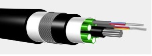
Figure: Single fiber and a sheath of three fibers
v An optical fiber consists of two concentric cylinders: an inner core surrounded by a cladding. Both the core and the cladding are made of transparent plastic or glass material. The core is used for guiding a light beam, whereas the cladding (which has a different refractive index) acts as a reflector to prevent the light from escaping from the core. Because optical fiber uses a light signal instead of electrons, it does not suffer from the various noise problems associated with electromagnetic signals. The signal is usually generated by a laser or Light Emitting Diode (LED). Optical fibers can provide bandwidth to distance ratios in order of 100s of MHz per kilometer. Like other cables, hundreds of optical fibers are usually housed within one cable. They are being increasingly used by telecommunication carriers for long distance 2 Crosstalk is the unwanted coupling effect between two or more signal paths, which causes signal distortion.
v Current trends promise that they will replace twisted pair residential loops in the near future.
v Fiber optic cable transmits light signals rather than electrical signals. It is enormously more efficient than the other network transmission media. As soon as it comes down in price (both in terms of the cable and installation cost), fiber optic will be the choice for network cabling.
v A light pulse can be used to signal a ‘1’ bit; the absence of a pulse signals a ‘0’ bit. Visible light has a frequency of about 108 MHz, so the bandwidth of an optical transmission system is potentially enormous. An optical transmission system has three components: the transmission medium, the light source and the detector. The transmission medium is an ultra-thin fiber of glass or fused silica. The light source is either a LED (Light Emit Diode) or a laser diode, both of which emits light pulses when a electrical current is applied. The detector is a photo diode, which generates an electrical pulse when light falls on it.
v There are two common types of fiber cables — single mode and multimode. Multimode cable has a larger diameter; however, both cables provide high bandwidth at high speeds. Single mode can provide more distance, but it is more expensive.
Advantages of Optical fibers.
v Fiber optic cable has the ability to transmit signals over much longer distances than coaxial and twisted pair
v It covers distance up to 2 Kms without a repeater.
v It also has the capability to carry information at vastly greater speeds.
v They use light which neither causes electrical interference nor are they susceptible to electrical interference
v They are manufactured to reflect the light inwards, so a fiber can carry a pulse of light further than a copper wire can carry a signal
v Light can encode more information that electrical signals, so they carry more information than a wire
v Light can carry a signal over a single fiber, unlike electricity which requires a pair of wires
Disadvantages of Optical fibers.
v Optical fiber cables are most expensive among all the cables.
v Installation and maintenance of coaxial cable is high.
v Glass fiber is more easily broken than wire
v Propagation of light is unidirectional. If we need bidirectional communication then two fibers are needed.
|
Summary of Cable Characteristics
|
||||
|
Cable
Type |
Cable
Cost |
Installation
Cost |
EMI
Sensitivity |
Data
Bandwidth |
|
UTPSTP Coax Fiber Optic |
LowestMedium Medium Highest |
LowestModerate Moderate Highest |
HighestLow Low None |
LowestModerate High Very high |
